Instructions
- Please submit a single PDF file on Canvas.
- If you have codes, please put them in the same PDF file.
- This homework is DUE on Feb. 1.
Disclaimer
Images for Problems 2 and 3 are taken from Shigley’s.
Problem 1 (10 Points)
For the plane stress $\sigma_x = -8MPa$, $\sigma_y = 7MPa$, $\tau_{xy} = 6MPa$ cw, draw a Mohr’s circle diagram properly labeled, find the principal normal and shear stresses, and determine the angle from the $x$ axis to $\sigma_1$. Draw stress elements as in Fig. 3-11c and d (Shigley’s) and label all details.
Problem 2 (30 Points)
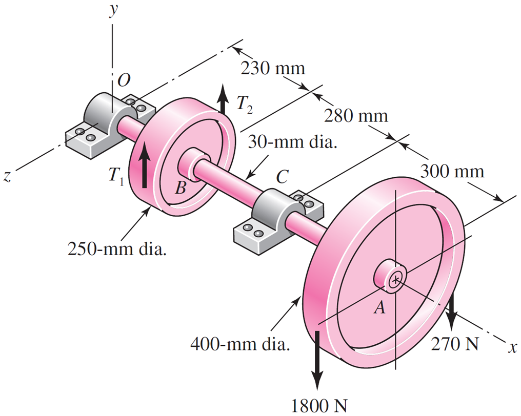
A countershaft carrying two V-belt pulleys is shown in the figure. Pulley A receives power from a motor through a belt with the belt tensions shown. The power is transmitted through the shaft and delivered to the belt on pulley B. Assume the belt tension on the loose side at B is 15 percent of the tension on the tight side.
-
Determine the tensions in the belt on pulley B, assuming the shaft is running at a constant speed.
-
Find the magnitudes of the bearing reaction forces, assuming the bearings act as simple supports.
-
Draw shear-force and bending-moment diagrams for the shaft. If needed, make one set for the horizontal plane and another set for the vertical plane.
-
At the point of maximum bending moment, determine the bending stress and the torsional shear stress.
-
At the point of maximum bending moment, determine the principal stresses and the maximum shear stress.
Problem 3 (20 Points)
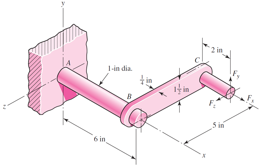
The cantilevered bar in the figure is made from a ductile material and is statically loaded with $F_y = 200lbf$ and $F_x = F_z = 0$. Analyze the stress situation in rod AB by obtaining the following information.
-
Determine the precise location of the critical stress element.
-
Sketch the critical stress element and determine magnitudes and directions for all stresses acting on it. (Transverse shear may only be neglected if you can justify this decision.)
-
For the critical stress element, determine the principal stresses and the maximum shear stress.
Problem 4 (20 Points for Part 1 and 2)
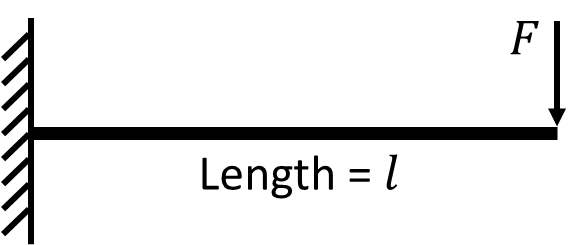
Consider a cantilever beam as shown in the figure with length $l$ and the left end fixed to a wall.
-
Derive the deflection $y$ of the beam along $x$ under a single downward force $F$ on the right, and assume that the moment of inertia $I$ is constant along $x$. (Show complete derivation instead of the final function $y(x)$)
-
Now consider that the beam has two connected parts, with the part on the left (of length $l/2$) having a moment of inertia $I_1$, and the part on the right $I_2$. Derive the deflection $y$ again. Ignore stress concentration.
-
Further, consider that the cross-sections for the two parts are both circular, and the total volume of the beam is constant. What should $I_1$ and $I_2$ be for the beam to have minimal maximum deflection? (Optional)
Problem 5 (20 Points)
-
Form your project team. Choose from one of these: (1) Shaft, (2) Gear + Bearing + key. Each team should have at most 5 people.
-
Formulate a pseudo code (flow chart) for component-wise analysis and design.
-
For shaft teams, please read Chapter 6 on Fatigue Failure Resulting from Variable Loading and Chapter 7 on Shafts and Shaft Components (Sections 7-4 to 7-5). Start with Example 7-2 that runs through the whole design process, list down the concepts you do not understand, and then seek answers to these questions from Chapters 6 and 7.
-
For gear+ teams, please read Chapter 13 Gears-General Sections 13-1 to 13-8 and 13-13 and Chapter 14 Spur and Helical Gears. For Chapter 14, start with Section 14-19 and the example within, list down the concepts you do not understand, and then seek answers from the chapter. For bearing and key, please read Chapter 11 on Rolling-Contact Bearings and Chapter 7 Section 7-7.
-
The pseudo code should specify (1) the inputs, e.g., static and dynamic loading conditions, geometry, target safety factors, (2) the outputs, e.g., detailed component geometry design, material selection, performance metrics, and (3) the design flow.
-
As a starting point, your submission does not have to be perfect but needs to show your best effort.