Problem 1 (20 Points)
Let’s use an overly simplified model to investigate the difference in side impact safety between a convertible and a regular car. Specifically, we consider the side panels and the roof panel as beams, each with length $l$, second-area moment $I$, cross-section area $A$, and Young’s modulus $E$.
- Derive the spring rate $k$ for the convertible. ($k=F/\delta$, where $\delta$ is the deflection due to $F$.) (5 Pts)
- Derive the free-body diagram for the regular car. (5 Pts)
- Derive the spring rate for the regular car, by assuming that the horizontal beam does not buckle. (10 Pts) Note: Need to take into account the compression of the horizontal beam.

Problem 1 Solution
-
For the convertible, $\delta = \frac{Fl^3}{3EI}$. The spring rate is $k = F/\delta = \frac{3EI}{l^3}$.
-
For the regular, the beam on the left has a deflection of $\delta_1 = \frac{(F-f)l^3}{3EI}$, where $f$ is the reaction force coming from the horizontal bar. The horizontal bar is under compression and is compressed by $\delta_2 = \frac{fl}{AE}$. The beam on the right has a deflection of $\delta_3 = \frac{fl^3}{3EI}$. From the geometric relationship $\delta_1 = \delta_2 + \delta_3$, we have
So the spring rate is \(k' = \frac{F}{\delta_1} = \frac{3EI}{(1 - \frac{l^2A}{(2l^2A + 3I)})l^3}.\)
We have $k < k’$.
Problem 2 (80 Points)
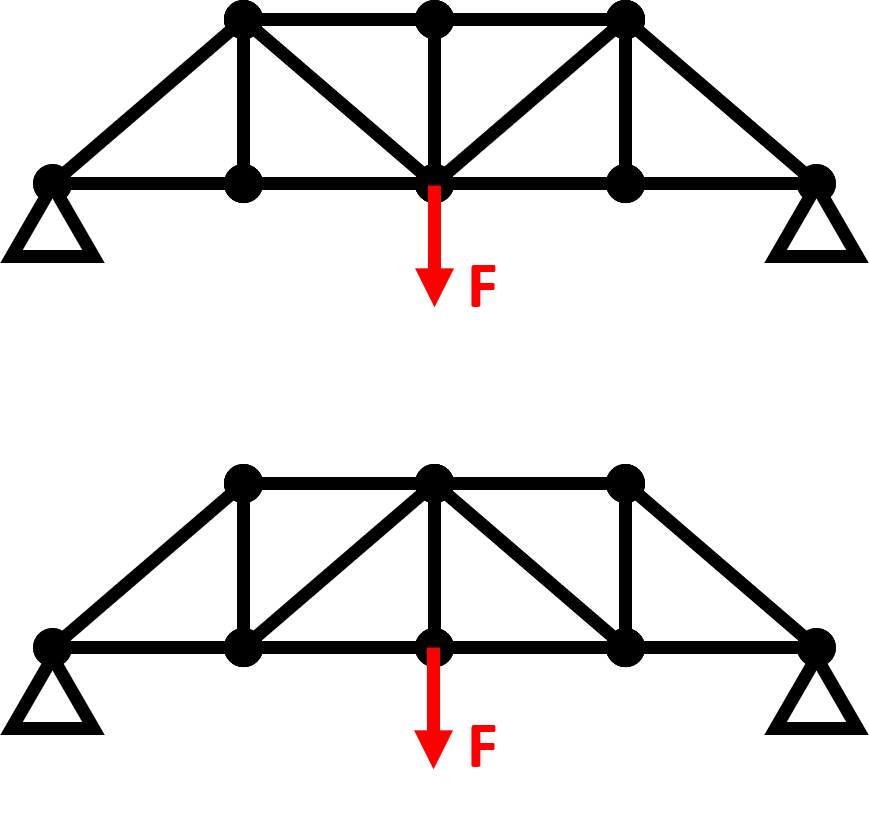
Consider the bridges in the figure. Assume all joints are frictionless (truss element). Find the deflections at the loading point given the loading and the truss members’ Young’s modulus and cross section area. If truss members fail due to large tensional stress, which bridge is a better design?

Problem 2 Solution
Please see tutorial for the sample code.
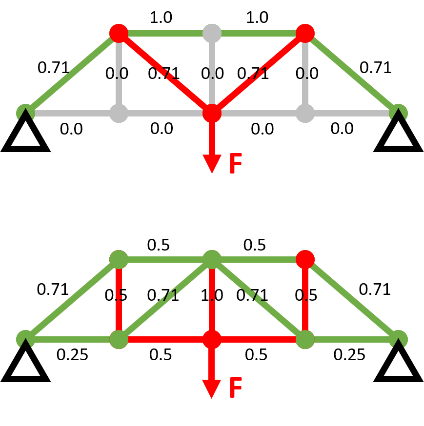
The following figure illustrates internal force in each member of the two designs. Green in compression, and red in tension.

By setting Young’s modulus and truss cross section area as 1s, the first bridge has a maximum deflection of 4.8 at the loading point. It has a maximum tension of 0.71 along the two diagonal members in red.
The second bridge has a maximum deflection of 5.1 at the loading point. It has a maximum tension of 1.0 along the central vertical member.
It should also be noted that compression members are usually made thicker to prevent buckling and therefore preferred to be shorter. Between the two designs, the first has less diagonal (longer) compression members.
Therefore, the first design is better. Please note that a more holistic evaluation should be done on all loading conditions specified for the bridge rather than a single load.