IoT - Flex Sensor Hookup Guide - MAE540-2017 Team 5
1.A narrative of the application
1.Robotics: Controlling joint movement or placement, bumper switches for wall detection 2.Bio metrics: Athletic equipment to indicate placement or movement 3.Virtual reality gaming gloves Could also be used in automotive and industrial controls, computer peripherals, joysticks, measuring devices, musical instruments, fitness products, etc
2. An introduction to the sensor
Flex sensors also called bend sensors, measure the amount of deflection caused by bending the sensor. This sensor is based on resistive carbon elements that achieve great form-factor on a thin flexible substrate. When the substrate is bent, the sensor produces a resistance output correlated to the bend radius-the smaller the radius, the higher the resistance value. A property of bend sensors is that bending the sensor at one point to a prescribed angle is not the most effective use of the sensor. As well, bending the sensor at one point to more than 90F may permanently damage the sensor. Instead, the sensor is bent around a radius of curvature.
Item list
You will need the following:
- The SparkFun ESP8266 Thing board
- FTDI Basic -3.3V
- SparkFun Cerberus USB Cable
- Jumper Wires and a Breadboard
- ** Flex Sensor 4.5” **
- Resistors
Hardware setup
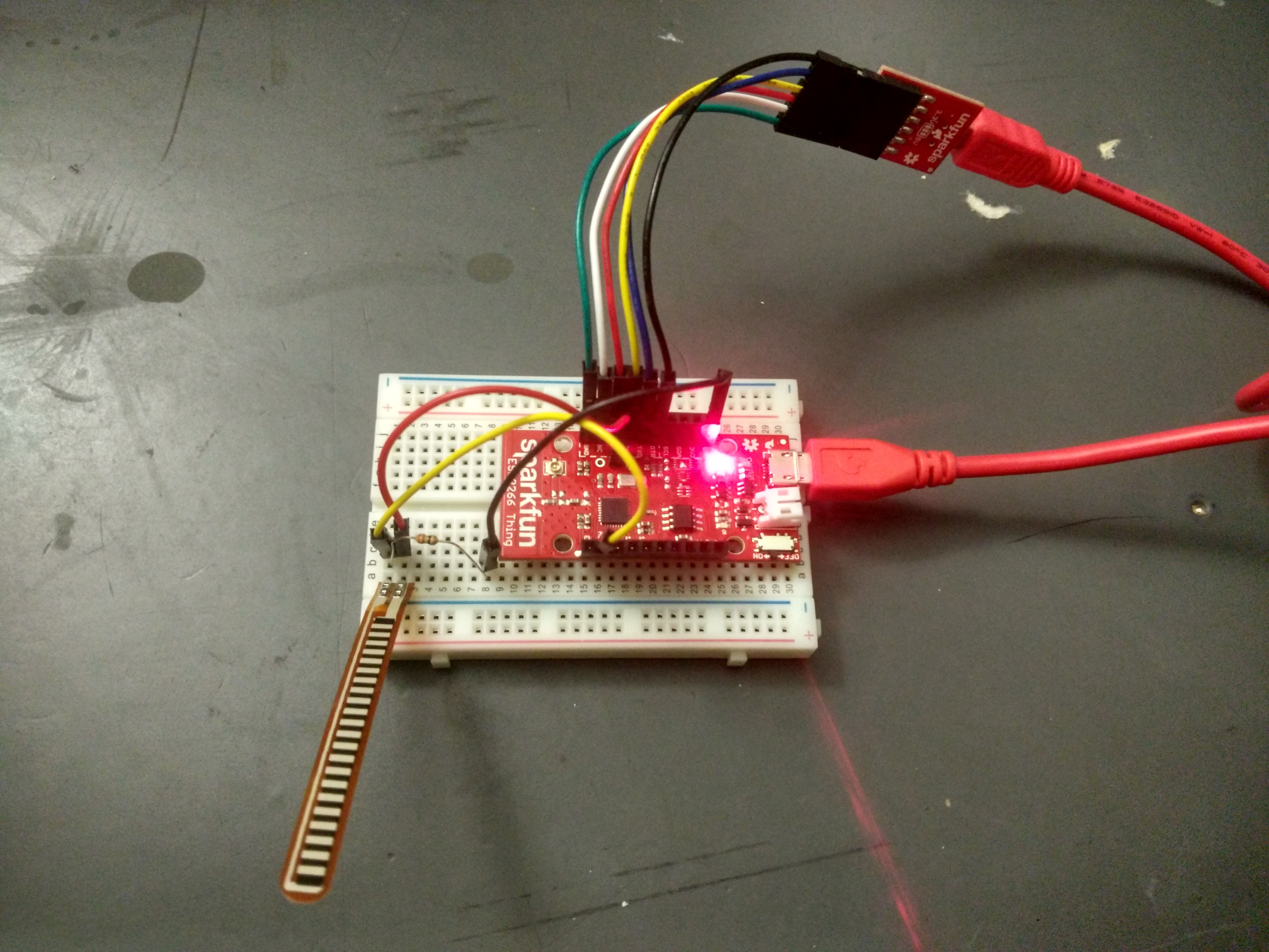
To test the basic functionality, we will use the following hookup.
Hookup
3. A schematic of the hookup
Schematic
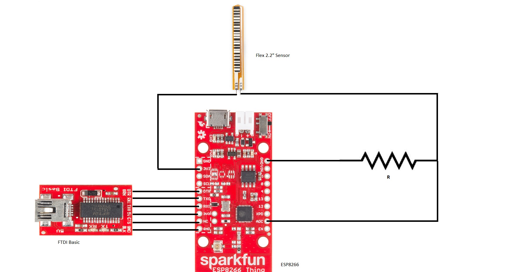
Connection between FTDI and ESP8266
FTDI | ESP8266 ———— | ————- DTR | DTR RX1 | TX0 TX0 | RX1 5V | 3V3 GND | GND
Connection between Flex Sensor and ESP8266
Flex Sensor | ESP8266 ———— | ————- One of the legs | 3V3 Second Leg | ADC
Resistor to be connected between GDC and ADC which will act as a voltage divider.
4. The Arduino code and related installation guide of necessary packages
Software setup
The following setup should work for both Windows and Linux.
- Download the Arduino IDE and install. It’s free.
- Open the Arduino IDE. Install ESP8266 Arduino Addon:
- Go to File > Preference, type
http://arduino.esp8266.com/stable/package_esp8266com_index.jsoninto the “Additional Board Manager URLs” text box. Hit OK. - Then go to Tools > Boards > Boards Manager, search “esp8266”, and install it.
- Go to Tools > Boards, select “ESP8266 Thing”. If you don’t see it, close and reopen the IDE.
- Go to File > Preference, type
A simple test
Here is a simple Arduino example based on the circuit above. Copy and paste this into your Arduino IDE, then upload!:
1
2
3
4
5
6
7
8
9
10
11
12
13
14
15
16
17
18
19
20
21
22
23
24
25
26
27
28
29
30
31
32
33
34
35
36
37
38
39
40
41
42
43
44
45
46
47
48
49
50
51
/******************************************************************************
Flex_Sensor_Example.ino
Example sketch for SparkFun's flex sensors
  (https://www.sparkfun.com/products/10264)
Jim Lindblom @ SparkFun Electronics
April 28, 2016

Create a voltage divider circuit combining a flex sensor with a 47k resistor.
- The resistor should connect from A0 to GND.
- The flex sensor should connect from A0 to 3.3V
As the resistance of the flex sensor increases (meaning it's being bent), the
voltage at A0 should decrease.

Development environment specifics:
Arduino 1.6.7
******************************************************************************/
constint FLEX_PIN = A0; // Pin connected to voltage divider output

// Measure the voltage at 5V and the actual resistance of your
// 47k resistor, and enter them below:
constfloat VCC =4.98; // Measured voltage of Ardunio 5V line
constfloat R_DIV =47500.0; // Measured resistance of 3.3k resistor

// Upload the code, then try to adjust these values to more
// accurately calculate bend degree.
constfloat STRAIGHT_RESISTANCE =37300.0; // resistance when straight
constfloat BEND_RESISTANCE =90000.0; // resistance at 90 deg

void setup()
{
Serial.begin(9600);
pinMode(FLEX_PIN, INPUT);
}

void loop()
{
// Read the ADC, and calculate voltage and resistance from it
intflexADC=analogRead(FLEX_PIN);
floatflexV=flexADC* VCC / 1023.0;
floatflexR= R_DIV * (VCC / flexV-1.0);
Serial.println("Resistance: "+String(flexR) +" ohms");

// Use the calculated resistance to estimate the sensor's
// bend angle:
float angle = map(flexR, STRAIGHT_RESISTANCE, BEND_RESISTANCE,
0, 90.0);
Serial.println("Bend: "+String(angle) +" degrees");
Serial.println();

  delay(500);
}
5. The experiment
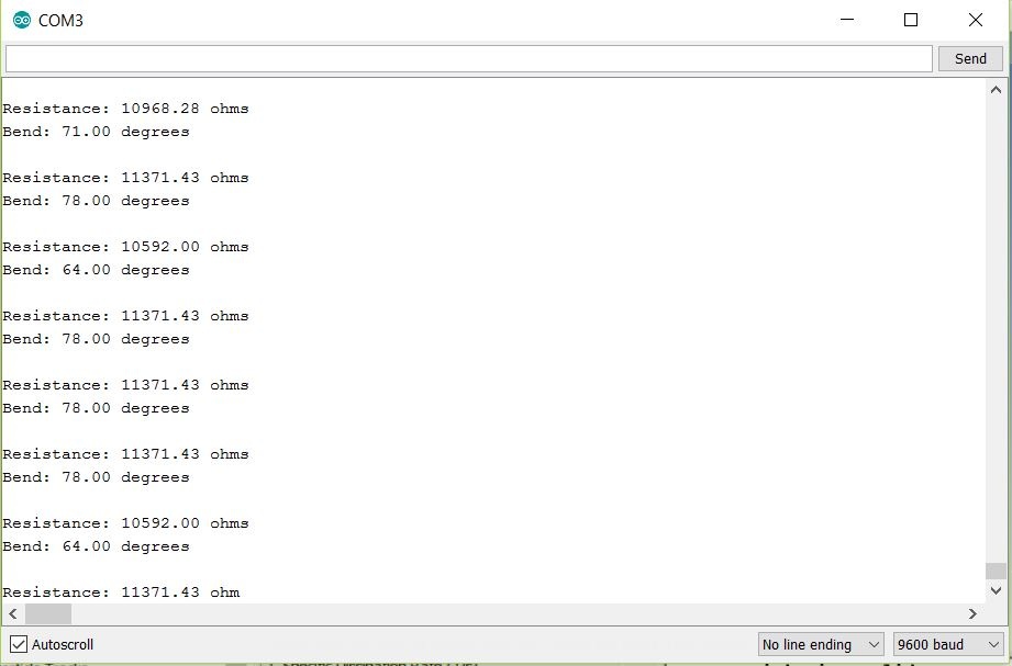
After uploading, open your serial monitor, and set the baud rate to 9600 bps.
If you bend the flex sensor, you should see resistance and estimated angle calculations change:
Results