IoT - PIR Motion Sensor hookup guide - MAE540-2017 Team 6
Things Required
- The SparkFun ESP8266 Thing board
- FTDI Basic -3.3V
- SparkFun Cerberus USB Cable
- Jumper Wires and a Breadboard
- PIR Motion Sensor
- An Android/Apple smart phone and a computer
Introduction
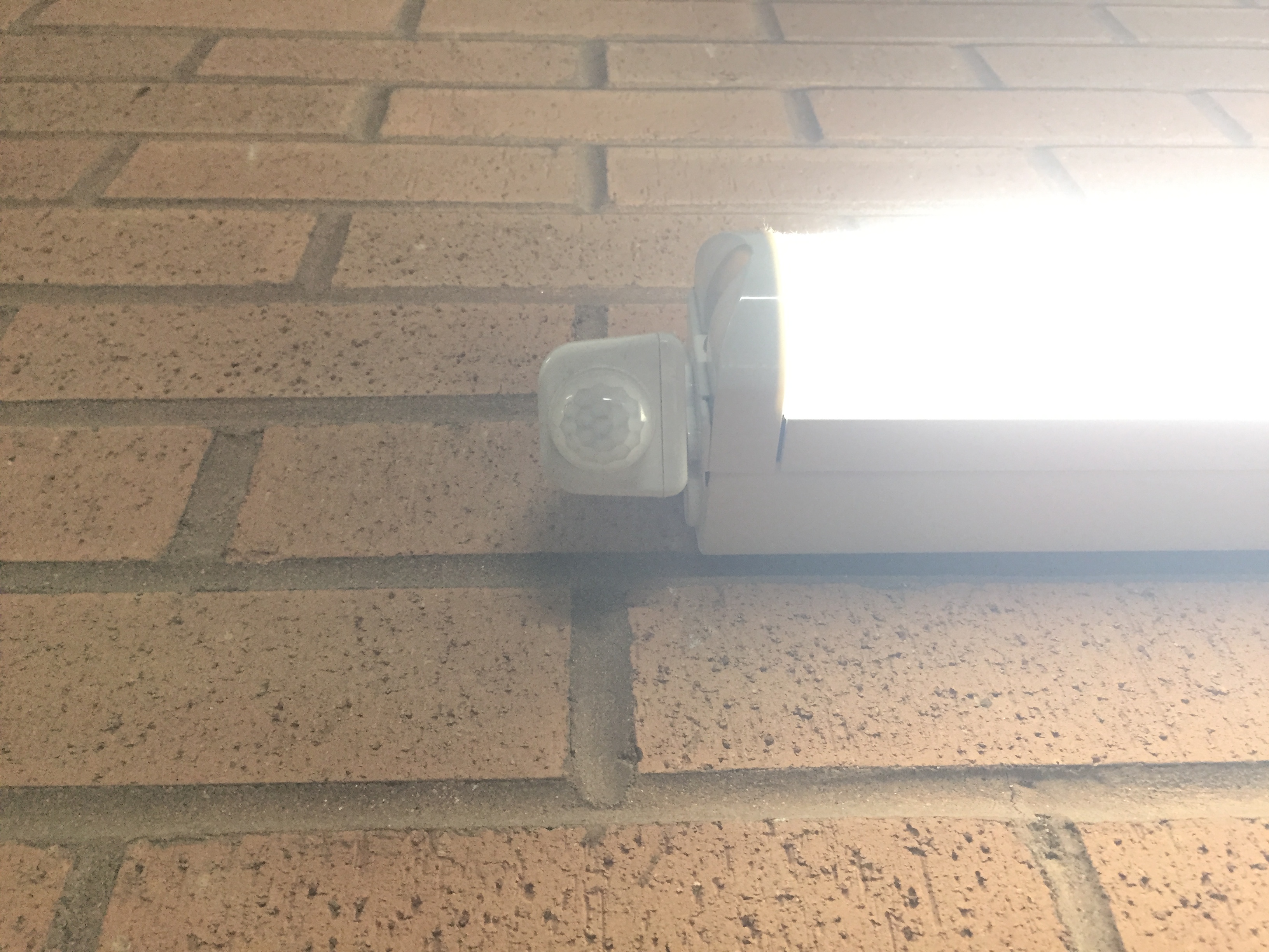
PIR Motion Sensor stands for Passive Infrared Sensor. The PIR sensor works by monitoring light in the infrared spectrum, PIR sensors can sense subtle changes in temperature across the area they’re viewing. When a human or some other object comes into the PIR’s field-of-view, the radiation pattern changes, and the PIR interprets that change as movement. That white cap dominating most of the top side of the PIR assembly is a lens, which helps focus the PIR sensor’s field-of-view. [1]
Applications of PIR Motion Sensor
The PIR Motion Sensor is used in the following applications:
- Security systems
- Energy saving applications
Energy saving application:
PIR sensors can be used to control the intensity of the light in the room/stairway thereby saving energy.

Whenever a person walks through the stairway, the PIR sensor detects the motion and sends a signal to the controller to increase the intensity of light in the stairway. When the stairway is empty, there is no motion detected by the PIR sensor, a signal is sent to the controller to decrease the intensity of light.
Sensor Hookup
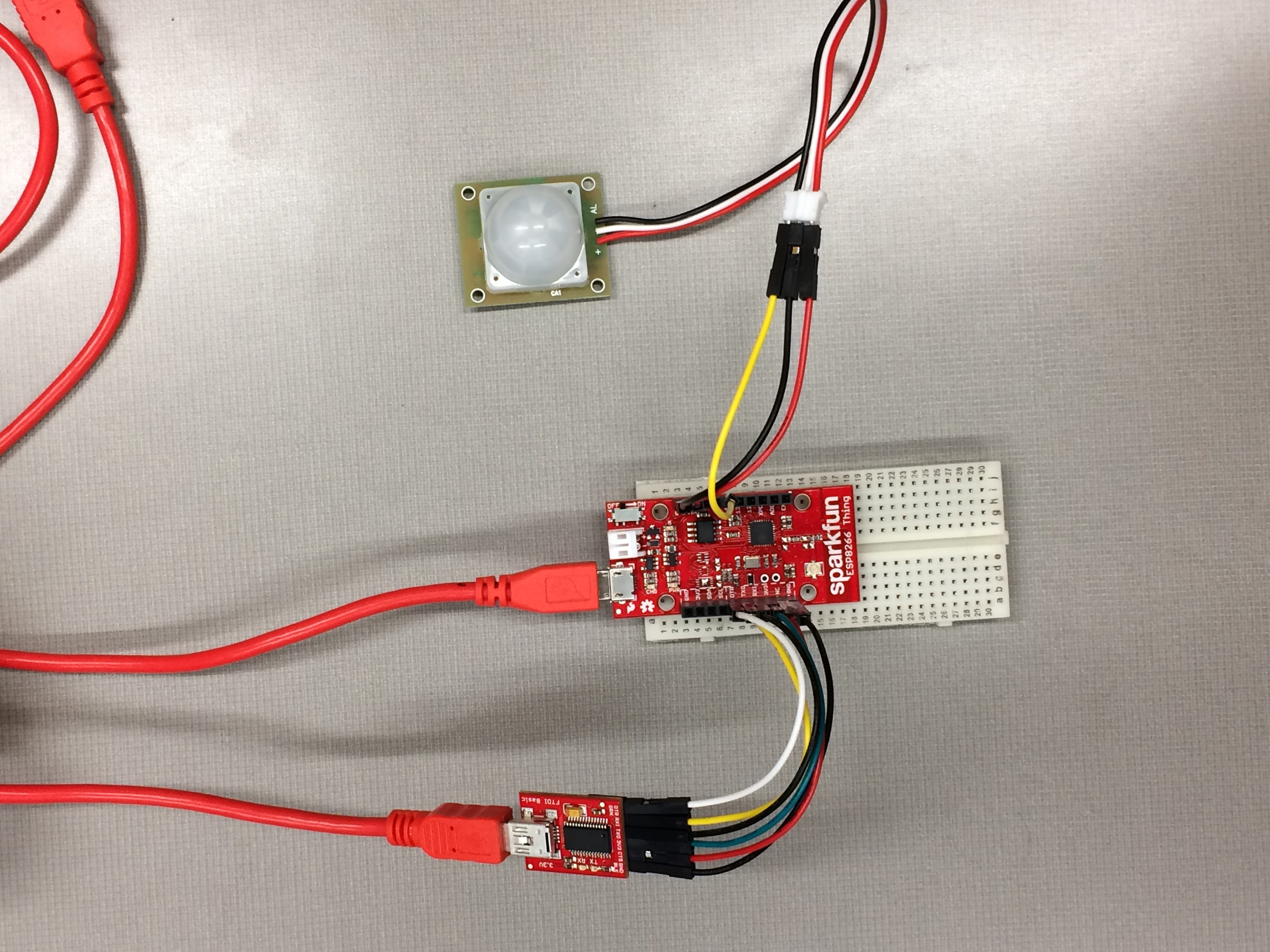
The sensor and FTDI setup are done as follows:
- Connect the FTDI chip to SparkFun ESP8266 Thing board
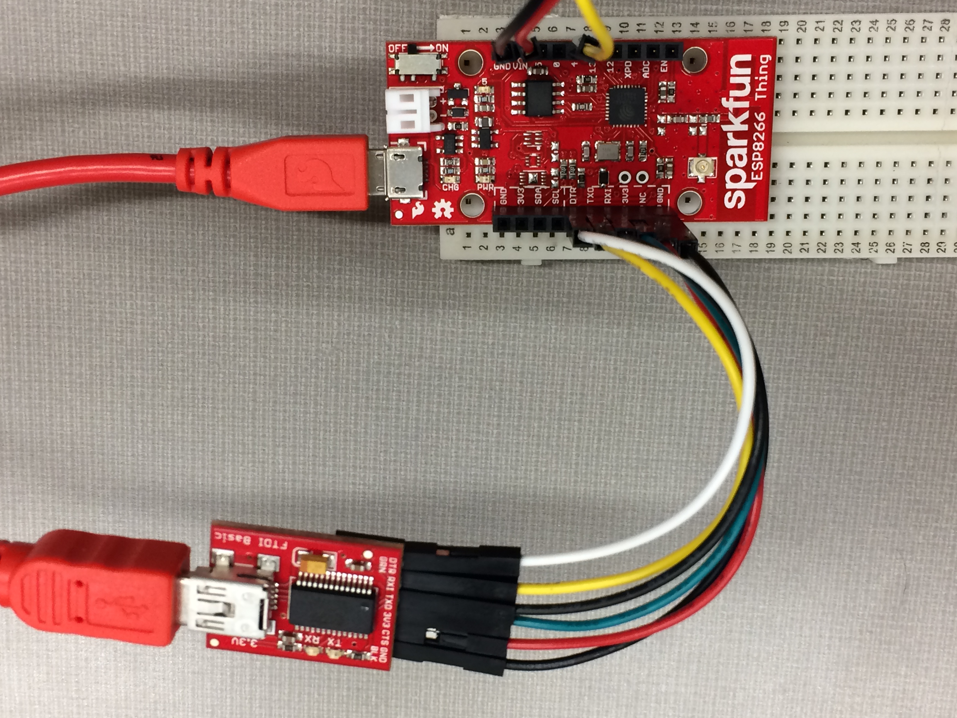
- Connect the PIR Motion Sensor to SparkFun ESP8266 Thing board as follows: a) Connect the Red (power) wire to VIN pin b) Connect the White (ground) wire to GND pin c) Connect the Black (alarm) wire to 4 pin
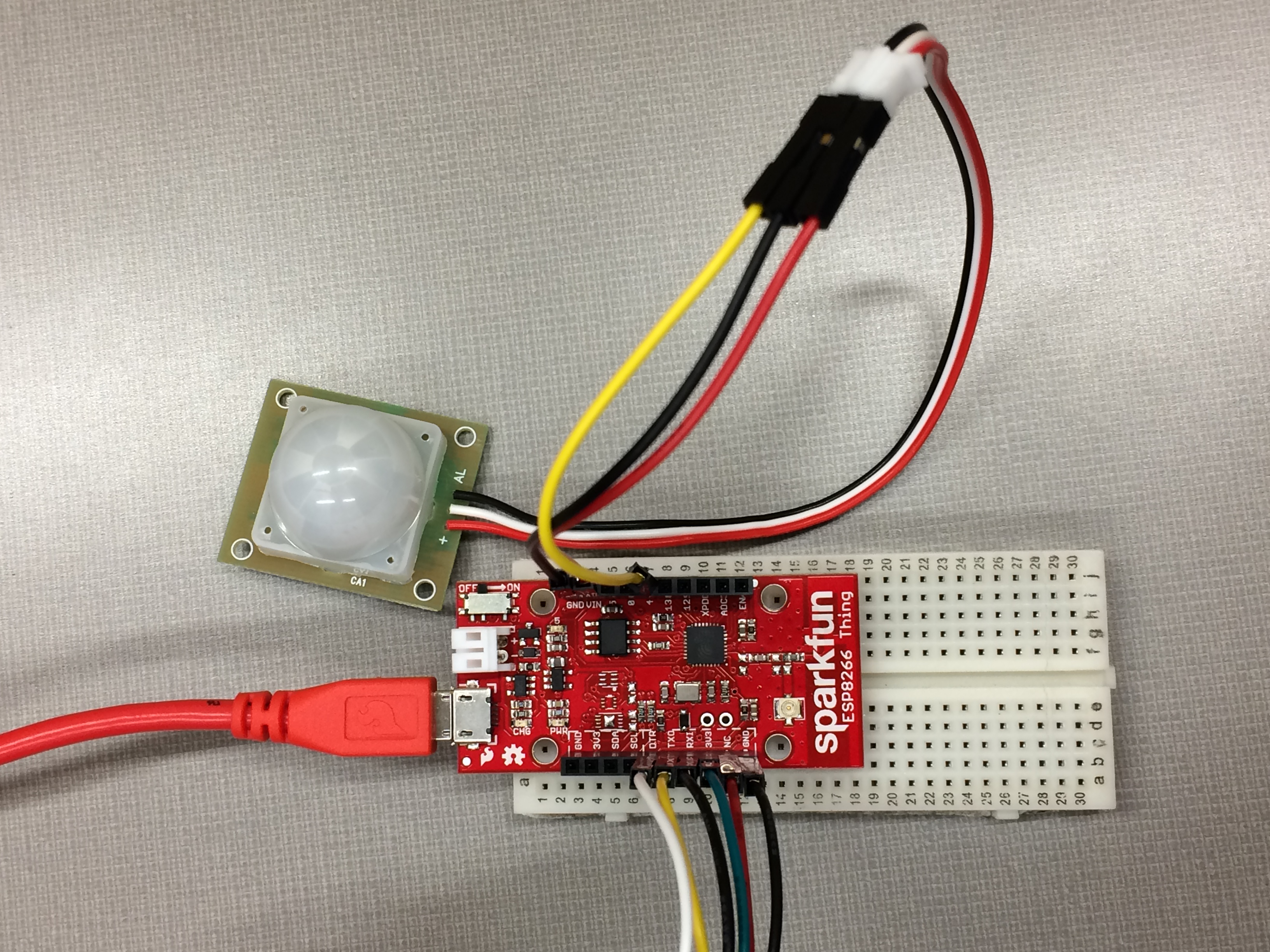
Ensure that the pins are connected properly! The hookup should look similar to this.
Software setup
- Download the Arduino IDE and install. It’s free.
- Open the Arduino IDE. Install ESP8266 Arduino Addon:
- Go to File > Preference, type
http://arduino.esp8266.com/stable/package_esp8266com_index.jsoninto the “Additional Board Manager URLs” text box. Hit OK. - Then go to Tools > Boards > Boards Manager, search “esp8266”, and install it.
- Go to Tools > Boards, select “ESP8266 Thing”. If you don’t see it, close and reopen the IDE.
- Go to File > Preference, type
- On your smart phone, install “Blynk” and register. It’s free.
- Download the [Blynk library][blynklib]. Unzip it and move it to %myDocuments%/Arduino/libraries (%myDocument% should be %your_user_name/documents% on Windows).[2]
Arduino Code
Create an Arduino sketch with the following code:
#include <Wire.h>
#include <ESP8266WiFi.h>
#include <BlynkSimpleEsp8266.h>
// You should get Auth Token in the Blynk App.
// Go to the Project Settings (nut icon).
char auth[] = "***"; // ***Type in your Blynk Token
// Your WiFi credentials.
// Set password to "" for open networks.
char ssid[] = "***";// ***your wifi name
char pass[] = "***";// ***and password
const int MOTION_PIN = 4; // Pin connected to motion detector
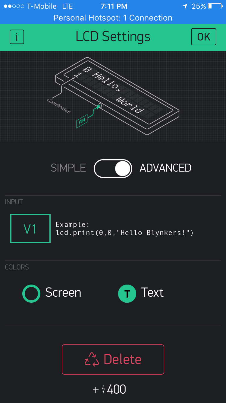
WidgetLCD lcd(V1);
void setup()
{
Serial.begin(115200);
Blynk.begin(auth, ssid, pass);
pinMode(MOTION_PIN, INPUT_PULLUP);
}
void loop()
{
Blynk.run();
int proximity = digitalRead(MOTION_PIN);
if (proximity == LOW) // If the sensor's output goes low, motion is detected
{
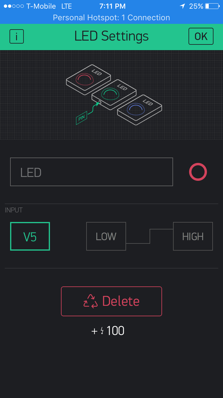
Blynk.virtualWrite(5,1023);
lcd.clear();
lcd.print(0,0,"Motion detected");
Serial.println("Motion detected!");
}
else
{
Blynk.virtualWrite(5,0);
lcd.clear();
}
}
Experiment and Discussion
After the hardware setup is done, on Blynk, add a “LED” and link it to Virtual Pin 5 (V5). Also add a “LCD” display and link it to Virtual Pin 1(V1).
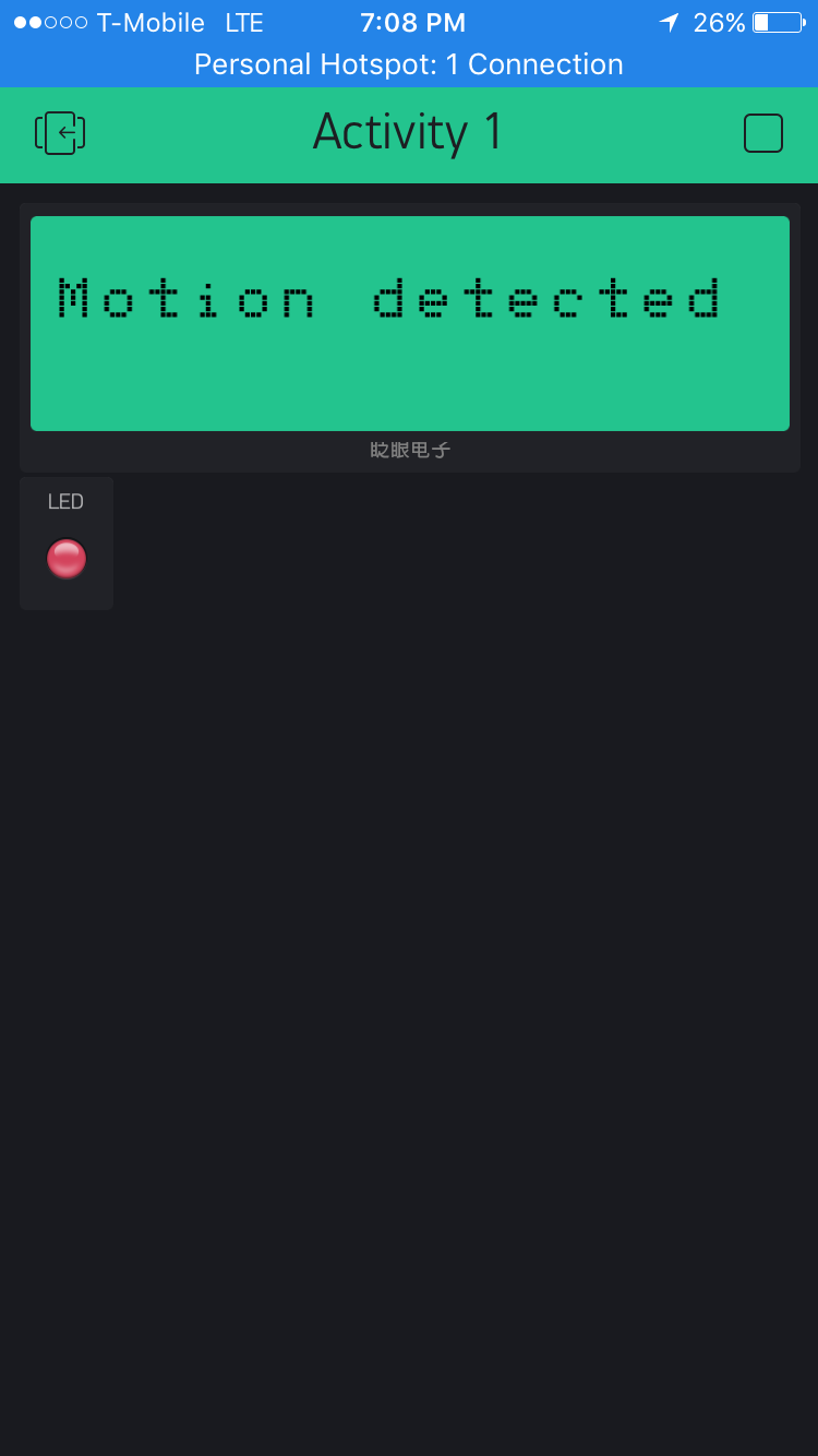
When motion is detected by the PIR sensor, the LCD displays “Motion Detected” and the LED turns ON.

When there is no motion, the LCD goes blank and the LED turns OFF.
Hint: If you encounter the error: “warning: espcomm_sync failed…”, there could be three reasons:
- Check if the Thing is turned on! The switch is on one corner of the board. You should see a red light on once the board is turned on.
-
In the IDE, check Tools>Port to see which serial port you are using. Remember that both the Thing and the FTDI are hooked up through USB, the one we should use is the USB Serial Port rather than Communications Port. To find the right port, go to Device Manager (on Windows, it’s under Control Panel>System and Security>System) and check “Ports”.
- It could be that your soldering is not well done.
In addition, sometimes this problem disappears when you re-upload, if your Port is chosen correctly.[2]
References
- https://learn.sparkfun.com/tutorials/pir-motion-sensor-hookup-guide?_ga=1.165380799.1629625605.1484697539
- https://github.com/DesignInformaticsLab/DesignInformaticsLab.github.io/blob/master/_posts/teaching/productdesign/2017-01-16-IoTlecture.md