IoT - Soil Moisture Sensor hookup guide - MAE540-2017 Team 2
INTRODUCTION
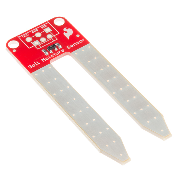
The soil moisture sensor is a simple device for measuring the moisture level in soil and similar materials. The soil moisture sensor is straight forward to use. The two large exposed pads function as probes for the sensor, together acting as a variable resistor. The more water that is in the soil or any other material means the better the conductivity between the pads will be and will result in a lower resistance, and a higher SIG out. To get the soil moisture sensor functioning we need to connect the VCC and GND pins to your Arduino-based device and you will receive a SIG out which will depend on the amount of water in the soil. A 3-pin jumper wire assembly is soldered onto the sensor for easy wiring. Use the Soil Moisture Sensor to:
- Measure the loss of moisture over time due to evaporation and plant uptake.
- Evaluate optimum soil moisture contents for various species of plants.
- Monitor soil moisture content to control irrigation in greenhouses.
- Enhance your Bottle Biology experiments.
HOW THE SENSOR WORKS
The Soil Moisture Sensor uses capacitance to measure dielectric permittivity of the surrounding medium. In soil, dielectric permittivity is a function of the water content. The sensor creates a voltage proportional to the dielectric permittivity, and therefore the water content of the soil.
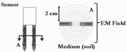
The sensor averages the water content over the entire length of the sensor. There is a 2cm zone of influence with respect to the flat surface of the sensor, but it has little or no sensitivity at the extreme edges. The figure above shows the electromagnetic field lines along a cross-section of the sensor, illustrating the 2cm zone of influence.
APPLICATION
Agriculture
- Measuring soil moisture is important for agricultural applications to help farmers manage their irrigation systems efficiently. Knowing the requirements of soil moisture conditions for the fields, enables the farmers to use lesser water and increase the yield and quality of the crop.
Landscape irrigation
- In urban and suburban areas, landscapes and residential lawns are using soil moisture sensors that interface with an irrigation controller.
** Connecting a soil moisture sensor to a simple irrigation clock will convert it into a “smart” irrigation controller that prevents irrigation cycles when the soil is already wet.
- Golf courses are using soil moisture sensors to increase the efficiency of their irrigation systems to prevent over-watering and leaching of fertilizers and other chemicals into the ground.
Research
- Soil moisture sensors are used in numerous research applications, e.g. in agricultural science and horticulture including irrigation planning, climate research, or environmental science including solute transport studies and as auxiliary sensors for soil respiration measurements.
- Simple sensors for gardeners
- Relatively cheap and simple devices that do not require a power source are available for checking whether plants to ensure sufficient moisture for their survival.
ITEM LIST
You will need the following:
- The SparkFun ESP8266 Thing board
- FTDI Basic -3.3V
- SparkFun Cerberus USB Cable
- Soil Moisture Sensor
- Jumper Wires and a Breadboard
- Arduino stackable header
- An Android/Apple smartphone and a computer
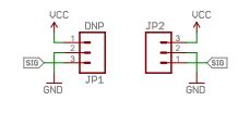
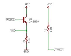
SCHEMATICS OF THE SENSOR
PROCEDURE
General procedure for using the Soil Moisture Sensor with ESP8266:
- Connect the ESP8266 to the bread board. The program to setup the ESP8266 and connecting to the Wi-Fi is shown below, Arduino code and installation guides Software setup
- Download the Arduino IDE and install.
- Open the Arduino IDE. Install ESP8266 Arduino Add-on: a. Go to File > Preference, type http://arduino.esp8266.com/stable/package_esp8266com_index.json into the “Additional Board Manager URLs” text box. Hit OK. b. Then go to Tools > Boards > Boards Manager, search “esp8266”, and install it. c. Go to Tools > Boards, select “ESP8266 Thing”. If you don’t see it, close and reopen the IDE.
- On your smartphone, install “Blynk” and register.
- Download the Blynk library. Unzip it and move it to %myDocuments%/Arduino/libraries (%myDocument% should be %your_user_name/documents% on Windows).
Code
1
2
3
4
5
6
7
8
9
10
11
12
13
14
15
16
17
18
19
20
21
22
23
24
#include <Wire.h>
#include <ESP8266WiFi.h>
#include <BlynkSimpleEsp8266.h>

char auth[] = "******"; //authentication code received from Blynk
char ssid[] = "********"; //wifi name
char pass[] = "********";//wifi password
int thresholdUp = ***; //Minimum value below which blynk notifies by E-mail
int sensorPin = A0;  //output ADC pin
void setup()
 {
   Blynk.begin(auth, ssid, pass);
 }

void loop()
{
 int sensorValue;
 sensorValue = analogRead(sensorPin);
 Blynk.run();
 if (sensorValue <= thresholdUp)
 {
   		Blynk.email("See ur plant", "Needs watering"); // Displaying output message
 	}
}
- Setting up the Blynk widgets, Blynk Setup: The setup part in the Blynk app is straight-forward. It needs two widgets to function, they are:
- Email widget
- Value Display New project is created as shown below,
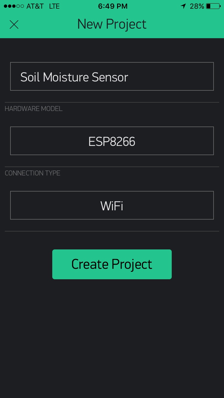
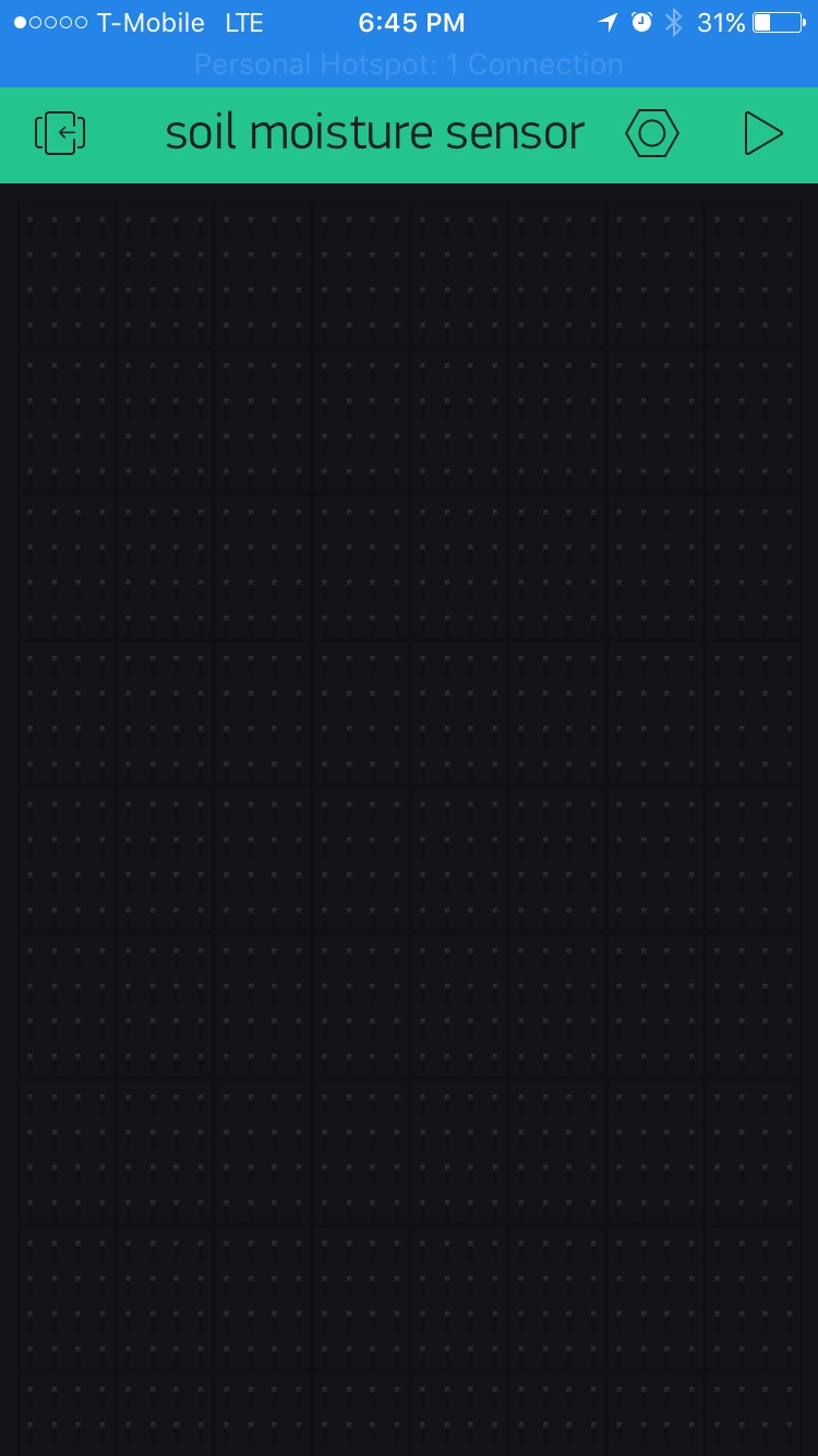
By swiping the screen on the new project window will open the widget window.
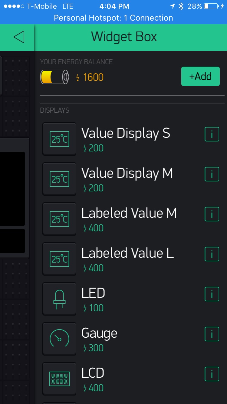
From that value display widget is selected. Name the input is mentioned as analog ADC0 pin. So, that the output of the pin is displayed directly.
- Soil moisture sensor was properly soldered and connected to ESP8266 using jumper wires.
- Setting up the sensor, Sensor Setup Follow the steps given below for testing the basic functionality of the board and the sensor. The Soil Moisture Sensor is very simple when it comes to hookup. You need to supply VCC and GND. We recommend not powering the sensor constantly to prevent oxidation of the probes. You will get a SIG out, which will be between almost VCC and GND, depending on the amount of water in the soil. The two probes are acting as a variable resistor - more water in the soil means better conductivity and results in a lower resistance and a higher SIG out. Your analog readings will vary depending on what voltage you use for Vcc as well as the resolution of your ADC pins. As for connecting the sensor to your circuit, we’ve given you a few different options. You can solder on a 3-pin JST Jumper Wire Assembly if you need to easily switch sensors on your project. This pairs nicely with our JST to Breadboard Jumper Connector.
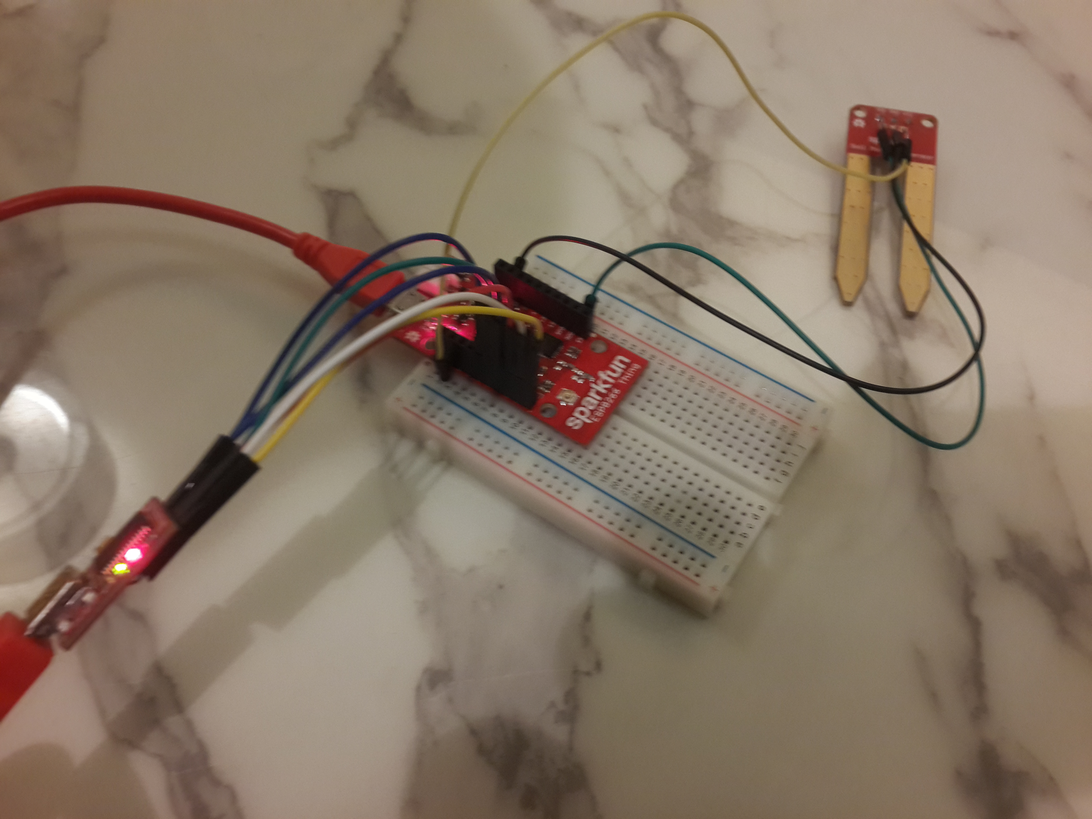
Another option is to solder on a 3-pin 3.5mm Screw Pin Terminal for a slightly more robust connection. You can always solder some hookup wire straight to the sensor. Hooking Up the Sensor to Thing Board: The three jumpers in the sensor are connected as follows: VCC—–>3V3 GND—->GND SIG—->ADC The below figure illustrates the connected sensor and the board.
EXPERIMENT
- We have set the minimum threshold value to 250 in the program code.
- Sensor was set based on the following instructions, Positioning the Sensor The prongs should be oriented horizontally, but rotated onto their side (like a knife poised to cut food) so that water does not pool on the flat surface of the prongs. The horizontal orientation of the sensor ensures the measurement is made at a particular soil depth. The entire sensor can be placed vertically, but because soil moisture often varies by depth, this is not usually the desired orientation. To position the sensor, use a thin implement such as a trenching shovel to make a pilot hole in the soil. Place the sensor into the hole, making sure the entire length of the sensor is covered. Press down on the soil along either side of the sensor with your fingers. Continue to compact the soil around the sensor by pressing down on the soil with your fingers until you have made at least five passes along the sensor. This step is important, as the soil adjacent to the sensor surface has the strongest influence on the sensor reading. Removing the sensor When removing the sensor from the soil, do not pull it out of the soil by the cable! Doing so may break internal connections and make the sensor unusable.
- Experimental Cases
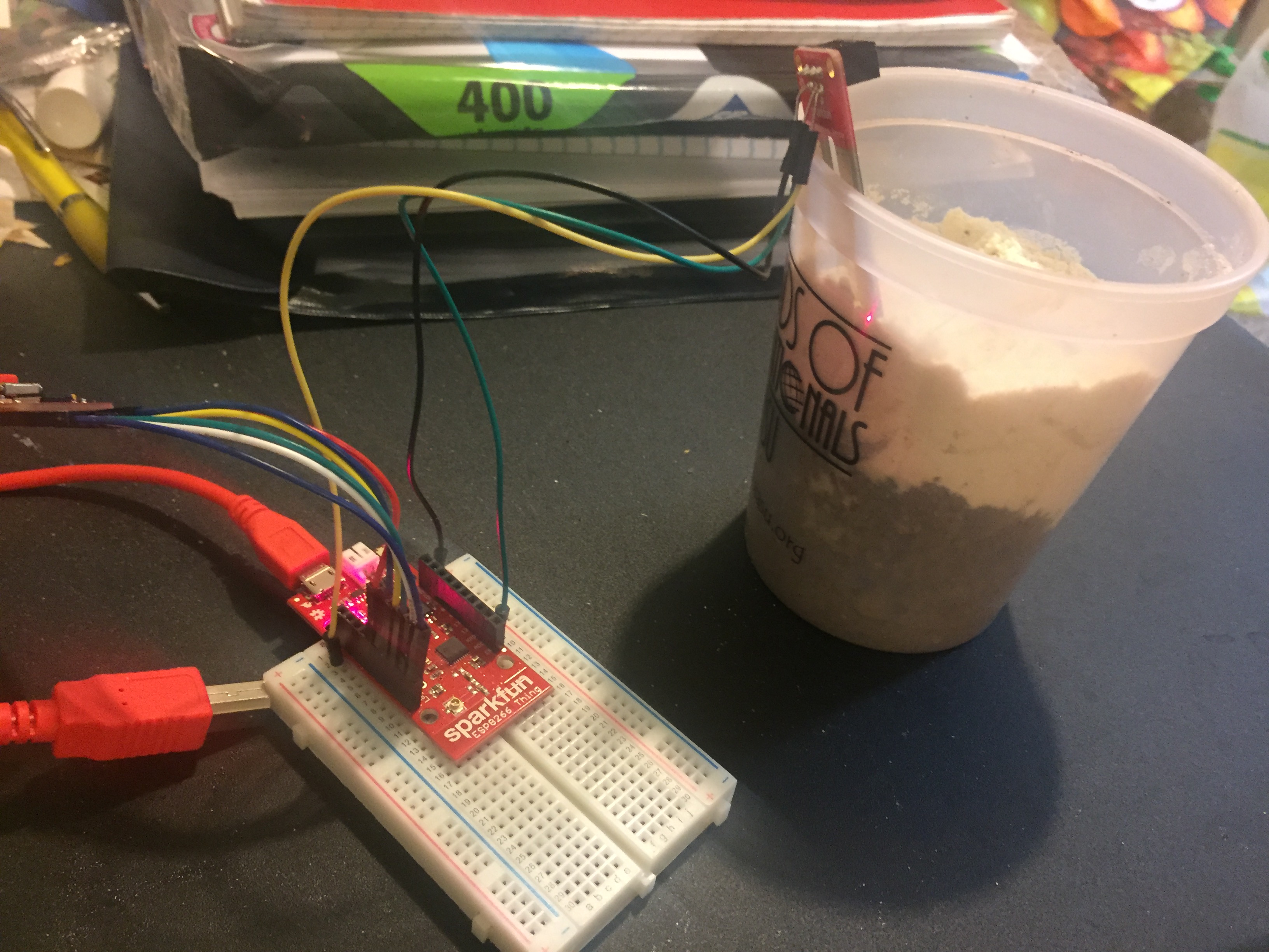
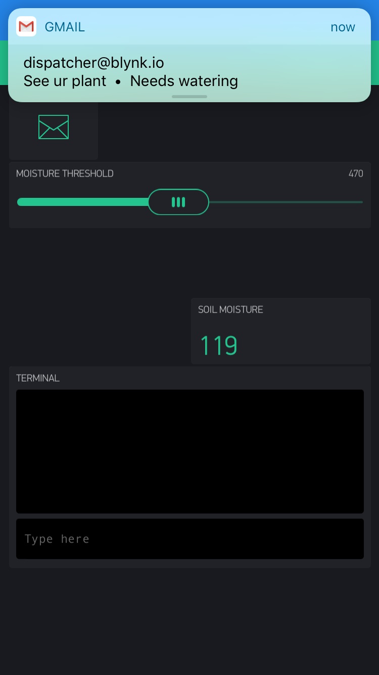
Case 1 - Dry Soil In the first case the Sensor was positioned in dry soil. Since the moisture content of the soil was less than the minimum threshold, a notification to water the plant was emailed to the set ID every 15 seconds.
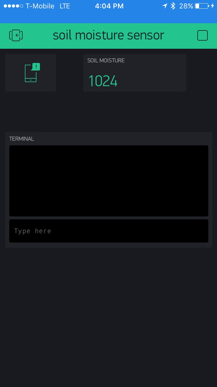
Case 2 - Wet Soil In the second case the sensor was positioned in wet soil. The moisture content of the soil can be observed from the Blynk app.
OBSERVATION
The sensor was used to monitor the moisture content in the soil. An alert was notified through E-mail when the moisture content of the soil dropped below the minimum threshold of 250 (Threshold can be set as per user requirement).