Topology Optimization in MATLAB
by Max Yi Ren
Introduction
This is a brief introduction to the DTU 2D topology optimization code from Dr. Sigmund’s group and the IUPUI 3D topology optimization code by Dr. K. Liu and Dr. A. Tovar. These are not necessarily the best tools to use for topology optimization, but if you already have MATLAB and want to quickly run some topology optimization cases, these are a good start.
At this moment, the tutorial will only focus on explaining the code, i.e., which parts of the code you should change to specify your boundary conditions and other parameters. I will extend it to include a brief intro of the theories and methodologies behind topology optimization later.
NOTE: Both codes we discuss here are for minimizing the structural compliance at equilibrium.
DTU 2D Topology Optimization Code
I will go through all the lines that you might want to tune for your own problem in the topology optimization code (top88.m).
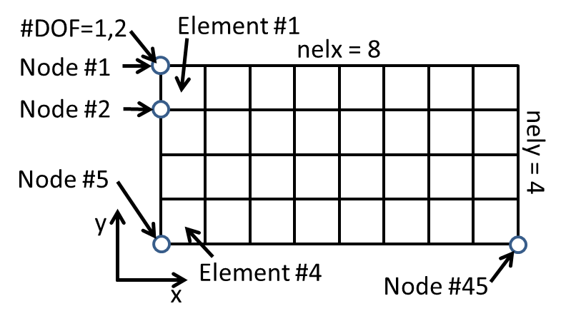
What directions are x and y and how are elements/nodes numbered?
The following figure answers these questions.
Line 1: Input parameters
function top88(nelx,nely,volfrac,penal,rmin,ft)The inputs are the number of elements in the x and y directions (nelx and nely, integers),
the volume fraction (volfrac, this is the number between 0 and 1 that specifies the
ratio between the volume of the target topology and the maximum volume $nelx \times nely$), the penalty
term for Young’s Modulus (penal, usually =3), the filter radius (rmin, usually =3),
and the method for filtering sensitivities (ft, either 1 or 2).
Line 3-6: Material properties
%% MATERIAL PROPERTIES
E0 = 1;
Emin = 1e-9;
nu = 0.3;
Set the Young’s Modulus (E0), and the Poisson’s ratio (nu). Leave Emin as a small number.
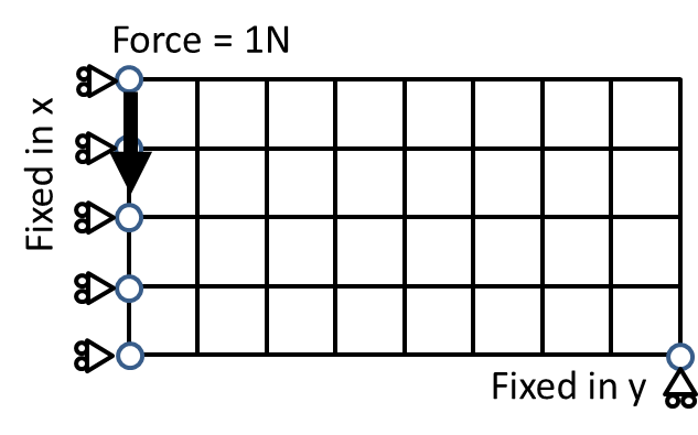
Line 19: Loadings
F = sparse(2,1,-1,2*(nely+1)*(nelx+1),1);This line specifies the loading. Here F is a sparse column vector with 2(nely+1)(nelx+1) elements.
(2,1,-1,\cdots) specifies that there is a force of -1 at the second row and first column
of the vector. According to the numbering convention of this code, this is to say that in the y direction
of the first node, there is a downward force of magnitude 1.
Line 21: Fixed DOFs
fixeddofs = union([1:2:2*(nely+1)],[2*(nelx+1)*(nely+1)]);This line specifies the nodes with fixed DOFs. [1:2:2*(nely+1)] are x directions
of all nodes to the left side of the structure, and 2*(nelx+1)*(nely+1) is the y direction
of the last node (right bottom corner). See figure below:
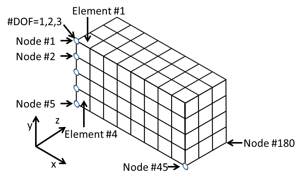
IUPUI 3D topology optimization code
The top3d.m is similar to top88.m notationally. The numbering convention is as follows:
Line 11-14 and 22: Loadings
% USER-DEFINED LOAD DOFs
[il,jl,kl] = meshgrid(nelx, 0, 0:nelz);                 % Coordinates
loadnid = kl*(nelx+1)*(nely+1)+il*(nely+1)+(nely+1-jl); % Node IDs
loaddof = 3*loadnid(:) - 1;                             % DOFs
F = sparse(loaddof,1,-1,ndof,1);Line 11-14 specifies the IDs of DOFs where loadings will be applied (loaddof). Line 22 then assigns
magnitudes of the loadings to these DOFS (y direction).
Line 15-18: Fixed DOFs
% USER-DEFINED SUPPORT FIXED DOFs
[iif,jf,kf] = meshgrid(0,0:nely,0:nelz);                  % Coordinates
fixednid = kf*(nelx+1)*(nely+1)+iif*(nely+1)+(nely+1-jf); % Node IDs
fixeddof = [3*fixednid(:); 3*fixednid(:)-1; 3*fixednid(:)-2]; % DOFs
fixeddof specifies the fixed DOFs. In this particular case, the boundary conditions are as follows:
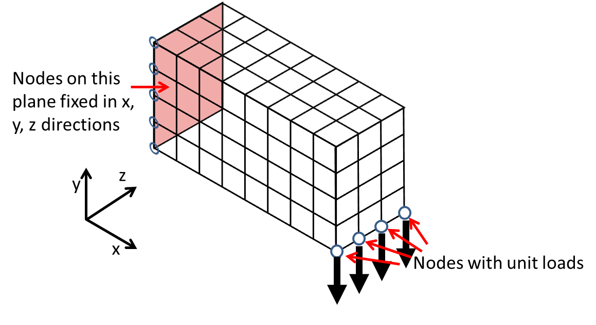
Practice
Use “top3d.m” to find the optimal topology for the following boundary conditions:
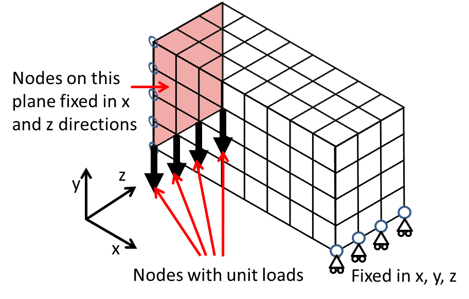
Solution: Replace the boundary condition with the following code:
% USER-DEFINED LOAD DOFs
[il,jl,kl] = meshgrid(nelx, 0, 0:nelz);                 % Coordinates
loadnid = kl*(nelx+1)*(nely+1)+il*(nely+1)+(nely+1-jl); % Node IDs
loaddof = 3*loadnid(:) - 1;                             % DOFs
% USER-DEFINED SUPPORT FIXED DOFs
% [iif,jf,kf] = meshgrid(0,0:nely,0:nelz);                  % Coordinates
[iif,jf,kf] = meshgrid(0,0,0:nelz);
fixednid = kf*(nelx+1)*(nely+1)+iif*(nely+1)+(nely+1-jf); % Node IDs
fixeddof = [3*fixednid(:); 3*fixednid(:)-1; 3*fixednid(:)-2]; % DOFs

% symmetry
[iif,jf,kf] = meshgrid(0,0:nely,0:nelz);
fixednid = kf*(nelx+1)*(nely+1)+iif*(nely+1)+(nely+1-jf)+nelx*(nely+1); % Node IDs
fixeddof = [fixeddof; 3*fixednid(:); 3*fixednid(:)-2]; % DOFs