IoT - SparkFun Sound Detector hookup guide - MAE540-2017 Team 3
A Narrative of the Application
Sound detecting sensors have a number of security related applications such as:
- Drone detection: Sound detecting sensors are used in detecting Drones as the drones emit some particular sound patterns which can be differentiated from the other common sounds such as vehicle horns, lawn mowers, etc. So the celebrities can now avoid the paparazzi cameras and we can get trespassing alerts for drones in restricted areas
- Gunshot Alert: Gunfire sounds also have a unique signature. this sensor is helpful in detecting the gunshots fired in public areas such as schools, clubs, religious spots, etc. So we can immediately find out the location of the incident and take action accordingly.
- Seismic detection: It also detects the vibrations from the ground or from the walls just before an earthquake and can literally save lives.
- Safe and vault: Many safes/vaults today, now comes equipped with an alarm which goes ON in case of any movement involving sound.
An Introduction to the Sensor:
The SparkFun Sound Detector is a compact board with a microphone which converts sound energy into electrical energy. The detector provides three outputs in the form of an analogue output of pitch labelled audio output, binary output to indicate the presence of sound. and an analogue representation of the amplitude called envelope output. The Sound Detector comes with a moderate sensitivity but we can change it according to our specific requirement by adding a through hole resistor to alter the gain.
Item list
You will need the following:
- The SparkFun ESP8266 Thing board
- FTDI Basic -3.3V
- SparkFun Cerberus USB Cable
- Jumper Wires and a Breadboard
- Arduino stackable header
- A Android/Apple smartphone and a computer.
Hardware Configuration of The Sound Detector.
SPECIFICATIONS:
Working Voltage: 3.5 - 5.5 V
Outputs: Audio output, envelope output and binary output.
Pins on Module - five: VCC / GND / Gate / Envelope / Audio
On-Board LEDs - Red LED, on when sound is detected.
Dimensions: 2.4cm X 4.4cm X 1 cm
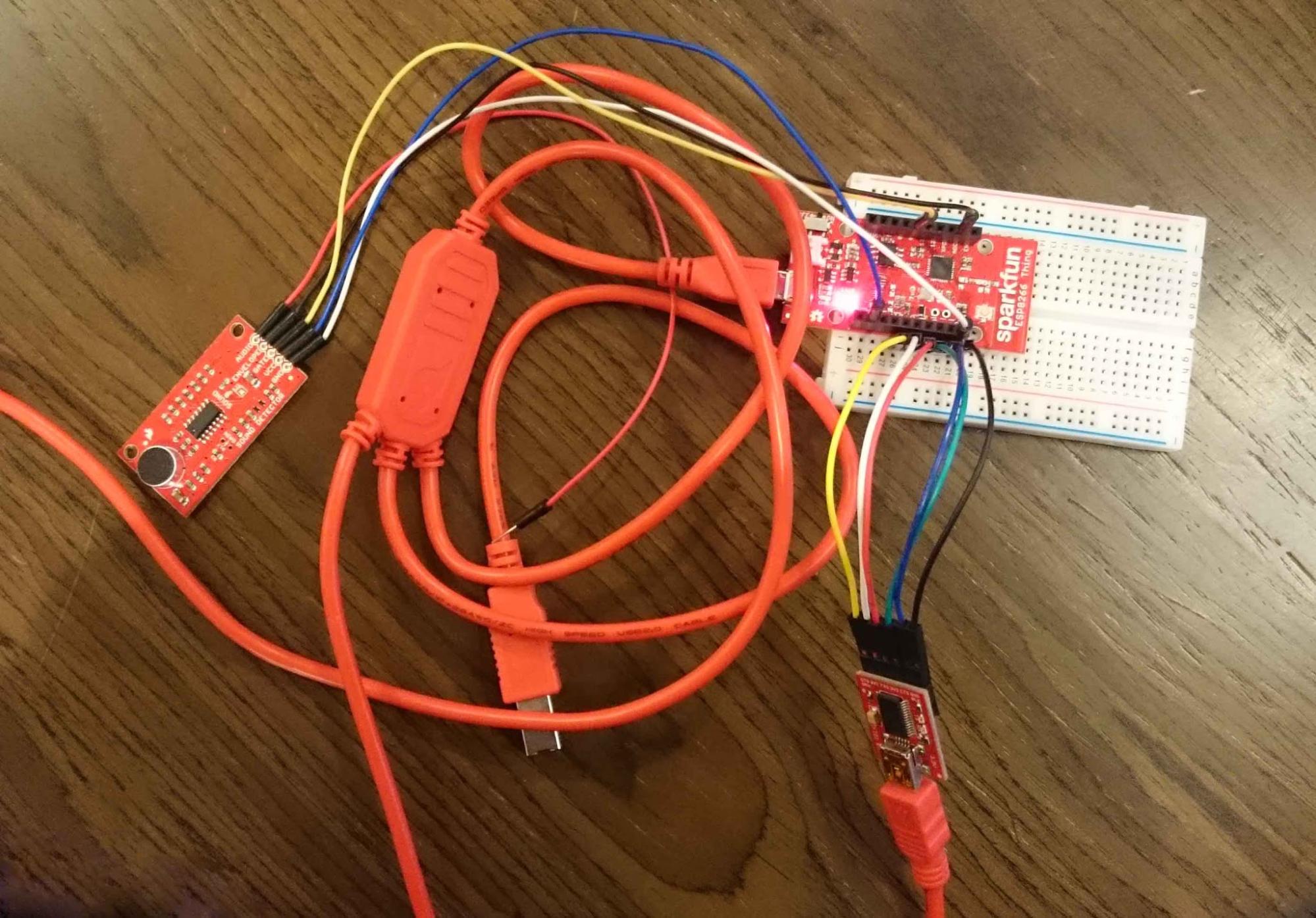
Hardware Setup
Also read: Hookup Guideline for ESP8266 Thing and Blynk
A Basic Functionality Test
For a basic functionality test of the Sound Detector, simply connect it this way.
(Sound Detector ? ESP8266 Thing )
GND ? GND.
VCC ? 3V3.
In a quiet room, power the board up, and then speak or preferably play some music close to the microphone. You should see the red LED on the Sound Detector board and the ESP8266 Thing blink in response to the sound.
Sound Detector Functionality Test
We can now test the board functionality: Using Blynk to switch turn on and off the sensor, to get the output readings of the presence of sound and the measurement of amplitude or pitch (depending on the hardware setup, as discussed in the instructions below) on Blynk. we will use the following hardware hookup to do so.
Hardware Setup Instructions;
- VCC on Sound Detector to 3V3 on ESP8266 Thing.
- GND on Sound Detector to GND on ESP8266 Thing.
- GATE on Sound Detector to PIN4 on ESP8266 Thing. 4.
- To measure Amplitude : GATE on Sound Detector to ADC A0 on ESP8266 Thing.
- To measure Pitch : AUDIO on Sound Detector to ADC A0 on ESP8266 Thing.
Arduino Sketch
For this particular sensor, no special library is needed.
In Arduino IDE, open a new sketch, compile and upload the following code:
1
2
3
4
5
6
7
8
9
10
11
12
13
14
15
16
17
18
19
20
21
22
23
24
25
26
27
28
29
30
31
32
33
34
35
36
37
38
39
40
41
42
43
44
45
46
47
48
49
50
51
 #include <Wire.h>

 #include <ESP8266WiFi.h>

 #include <BlynkSimpleEsp8266.h>

 #define PIN\_GATE\_IN 4

 // You should get Auth Token in the Blynk App.

 // Go to the Project Settings (nut icon).

 char auth[] = "\*\*\*";         // \*\*\*Type in your Blynk Token

 // Your WiFi credentials.

 // Set password to "" for open networks.

 char ssid[] = "\*\*\*";        //\*\*\* Enter your WiFi SSID here

 char pass[] = "\*\*\*";        // \*\*\*Enter your WiFi Password here

 void setup()

 {

                    Blynk.begin(auth, ssid, pass);

                    pinMode(PIN\_GATE\_IN,INPUT);

 }

 WidgetLED led1(V0);

 void loop()

 {

                    Blynk.run();

                    int x=digitalRead(PIN\_GATE\_IN);

                    if (x == 1)

                    led1.on();

                    else

                    led1.off();

 }
Following is a brief explanation of this code:
Line 1: Wire.h is necessary to work with the sensor (anything connected to SDA/SCL pins)
Line 2-3: These are header files for the ESP8266 Wifi shield and Blynk
Line 4: Defines Pin 4 as PIN_GATE_IN
Line 8: Helps identify the Blynk app using auth token code of the created project.
Line 11-12: Provides necessary wifi-hotspot name and corresponding password for wifi module to connect to the device.
Setup code: Passes the necessary information to Blynk to make connection and sets pin 4 as INPUT.
Line 21: Defines Virtual LED on Blynk V0 as led1
Loop code: Connects to Blynk and reading the Pin 4 decides to on or off the virtual LED
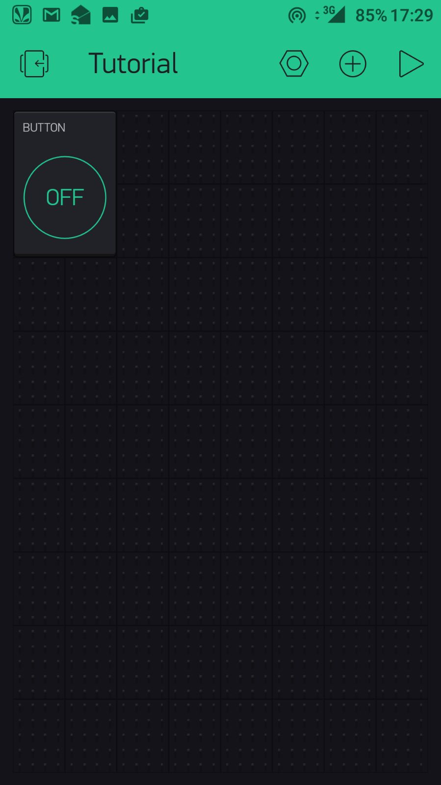
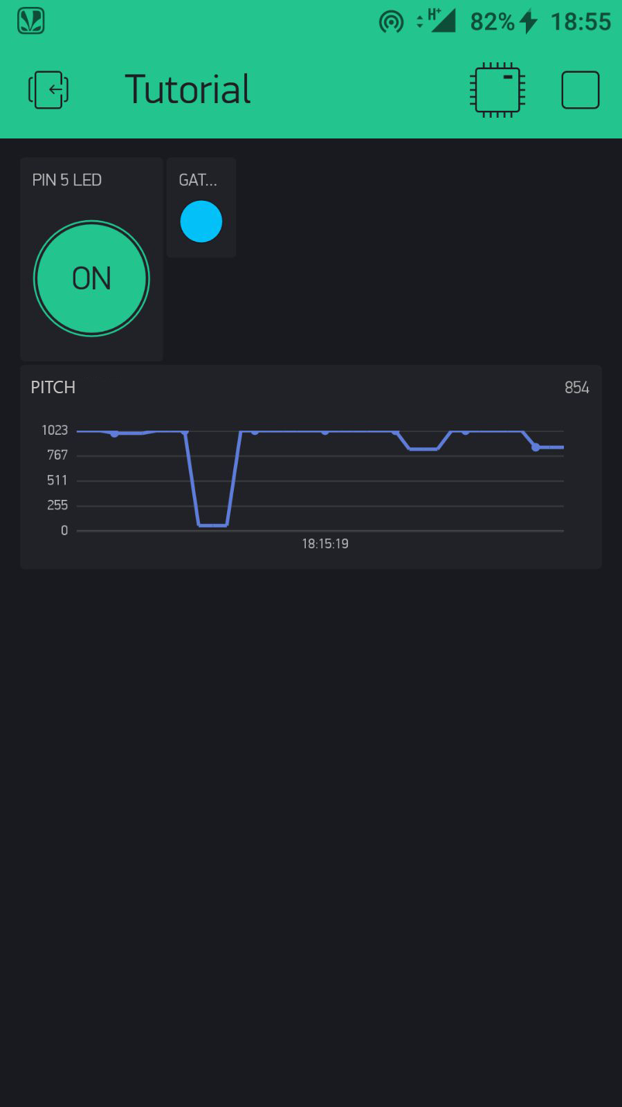
On Blynk, from Widget Box, add a "Button". This is to turn the sensor on and off.
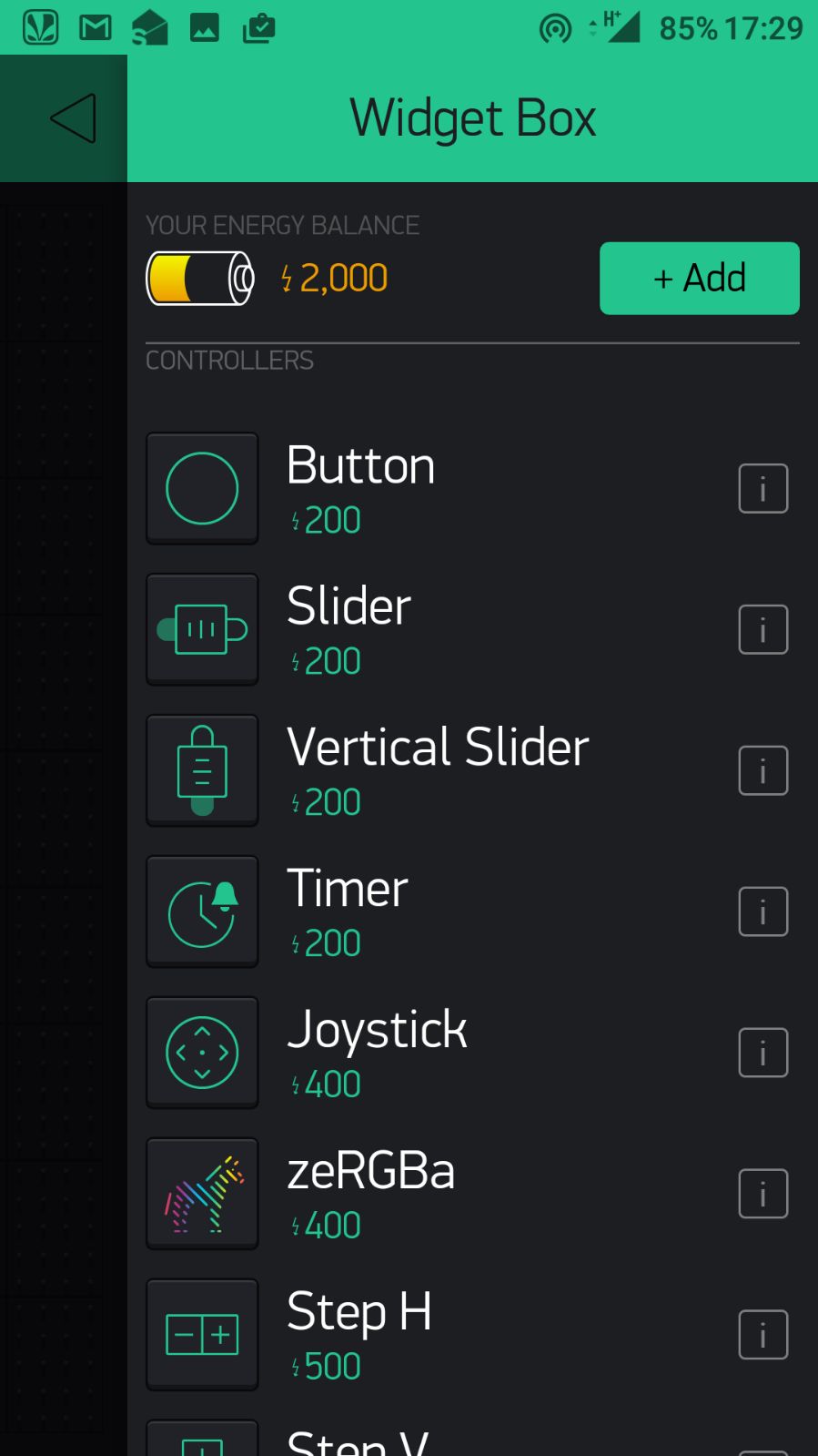
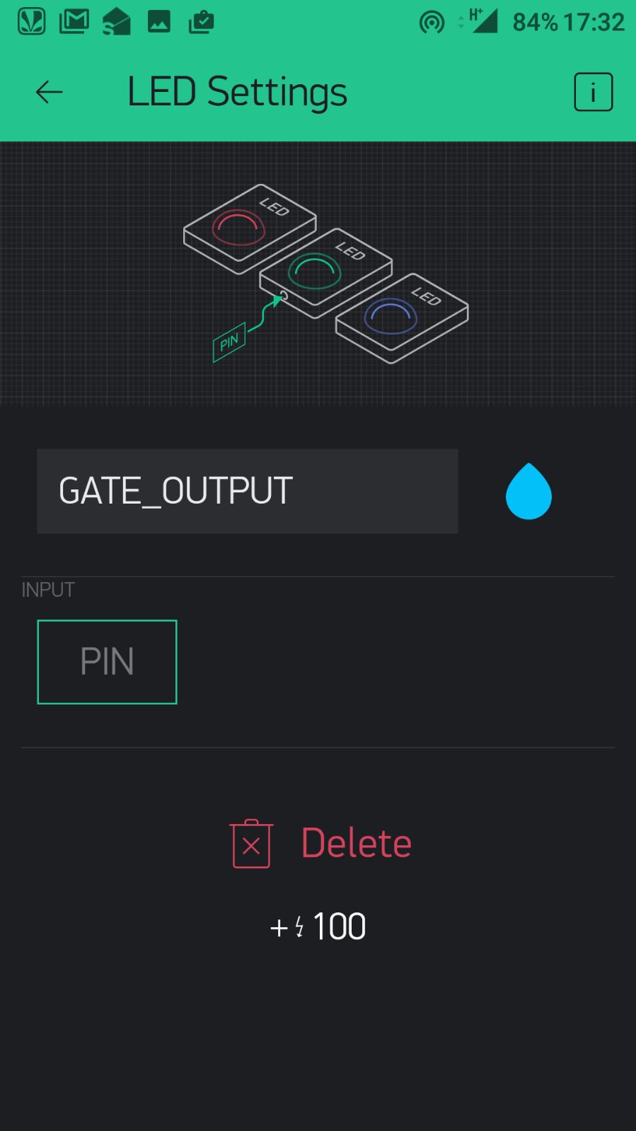
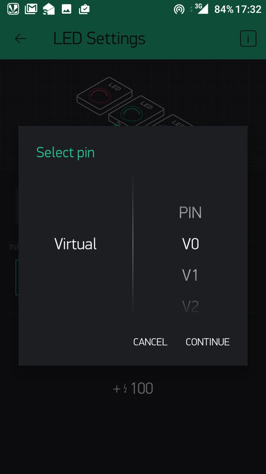
To get the GATE output on Blynk, from Widget Box, add an "LED". Name it as "Gate_Output" and select "Virtual V0" pin.
To plot graph of amplitude over time, from Widget Box in Blynk, select graph from menu, name it as "Amplitude", set input to ADC0 and reading frequency to 250ms.
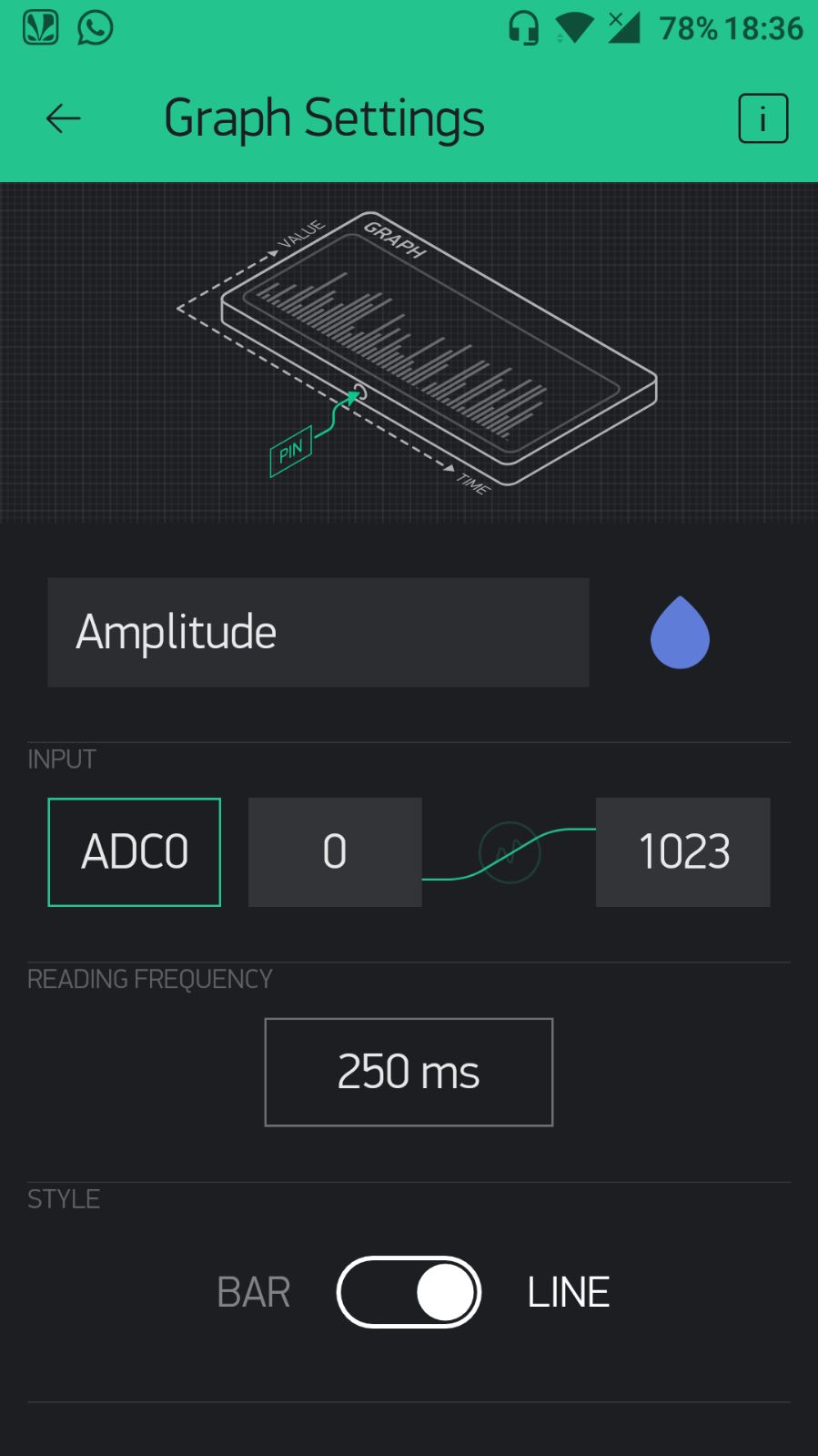
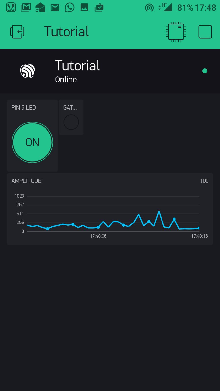
The output we got is shown in the picture above on the right.
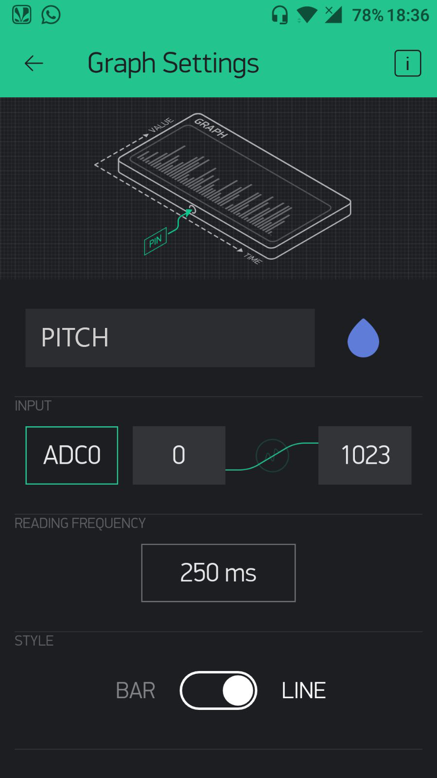
To plot graph of pitch over time, change the hardware connection as described in the hardware setup above and from the Widget Box in Blynk, select graph from menu, name it as "Pitch", set input to ADC0 and reading frequency to 250ms as before.
The experiment was done to check the output from the Audio Gate and Envelope. Also Button, Virtual LED and Graph widgets on Blynk.